Greater Tulsa Area Classifieds Moderated Newsgroup > Sapulpa
> 3 3/4 auto range RS232 multimeter w/ clamp dc up to 10A
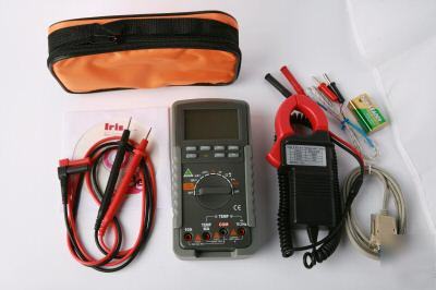
3 3/4 auto range RS232 multimeter w/ clamp dc up to 10A
item photo item photo item photo
New RS232 interface auto-range 3 3/4 LCD digital Multimeter with Clamp
3 3/4 digital LCD with 25 high numerals
Product size:165mm x 81 x 41mm
Battery:9V (NEDA1604/6F22)
AC measurement: average RMS
Display: 3-3/4 digits LCD with 25mm high numerals.
Auto Functions: Auto-zero, Auto-polarity, Auto-range
Auto power off: 30 minutes after stopping the switch or no push button, the
meter enter to Power off mode.
Safety Standards: The meter is up to the standards of IEC1010 Double
Insulation, Pollution degree 2 Overvoltage Category.
Operating Environment: 0C to 40C at ≤75% relative humidity.
Storage Environment: -20C to 60C at ≤80% relative humidity .
2.2. MEASUREMENT SPECIFICATION
Accuracies are ±(% of reading + number of digits),
Over load Protection: 1000V DC/750V AC.
Input impedance: ≥100MΩ on 400mV range
Over load Protection: 1000V DC/750V AC.
Input impedance: ≥100MΩ on 400mV range
Frequency: 400mV,750V at 50Hz~100Hz;
Frequency: 400uA~400mA at 50Hz~500Hz;
Display: Average RMS ACA by clamp
Overload Protection: 1000Arms.
Overload protection: 250V DC/250Vrms AC.
Overload protection: 250V DC/250Vrms AC
Note: Only AUTO range function
Overload protection: 250V DC/250Vrms AC
Frequency Range, Duty test Min Pulse width: 100nS
Hz/Duty Key Control, Duty test Min Pulse Width: 1uS
Note: Only AUTO range function.
TEMPERATURE (NiCr-NiSi SENSOR)
Overload protection: 250V DC/250Vrms AC
DIODE TEST AND CONTINUITY TEST
Overload protection: 250V DC/250Vrms AC
Push key to the choose function while Function
rotary switch is at the same position. Push the key and power on,
Push the key to select manual mode, push it again to change the
ranges, Press and Hold down for two seconds to exit manual mode.
But Hz/Duty and Capacitance no manual mode.
Push the key present display value will be stored in memory, new
display value is the difference between input value and stored data.
Push the key to lock display value, and the DH symbol will appear, push it
Push the key to change now function to Frequency Test and Push
it again to Duty test at DCV, ACV, DCA, ACA, Hz. Frequency RANGE,
test ,Push it again to Frequency test.
Push the key to enable RS232 output, then measurement value can be sent
to other equipment with RS232. the meter supply the file with measurement
value sent to a computer in the CD.
Push the Key to light the back light then it Will auto light off after
4.2.The markã€or sign〠next to the test lead jacks, is for warning that the
input voltage or current should not exceed the indicated values, this is to
prevent damage to internal circuitry.
4.3.The Function rotary switch and SELECT key should be set to
the range to be used before operation.
4.4.1 Connect the BLACK test lead to the "COM" jack and the RED
4.4.2 Set the Function rotary switch to "V≂" position, the sign
"AUTO"ã€"mV" will appear on display.
4.4.3 Connect the test leads across the source or load, and the
4.5.1 Connect the Black test lead to the "COM" jack and the RED
4.5.2 Set the Function rotary switch to "V≂"position and Push
SELECT key, the sign "AUTO"〠"AC"ã€"V" will appear on display.
4.5.3 Connect the test leads across the source or load, and the
measurement value appear on display. If AC voltage is under 400mV, Push
RANGE key until "AC", "mV" will appear on display.
4.6.1 Connect the BLACK test lead to the "COM" jack and the RED
test lead to "mA/Temp" jack for a maximum of 400mA, for a maximum
of 10A, move the RED test lead to "10A" jack.
4.6.2 Set the Function rotary switch to "mA≂"position for a maximum
of 400mA. for a maximum of 4000uA, rotate the FUNCTION rotary switch to
"uA≂" position. for a maximum of 10A, rotate the Function rotary
4.6.3 Connect the test leads across the source or load, and the
measurement value appear on display.
4.7.1 Connect the BLACK test lead to the "COM" jack
and the RED test lead to "mA/Temp" jack for a maximum of 400mA,
for a maximum of 10A, move the RED test lead to "10A" jack.
4.7.2 Set the Function rotary switch to "mA≂" position for a maximum
of 400mA. for a maximum of 4000uA, rotate the Function rotary
switch to "μA" position, for a maximum of 10A, rotate the Function
rotary switch to "10A≂", Then push SELECT key, the sign "AC" will appear on display.
4.7.3 Connect the test leads across the source or load, and the
measurement value appear on display.
4.7.4 TEST AC 400A or 1000A with the current clamp (A8,A9 Only)
adjunct: please Set the Function rotary switch to "ACA by clamp"
position, Connect the BLACK pin of the clamp adjunct to the "COM"
jack and the RED pin to the "mA/Temp" jack, then use the wire of
tested drill through the clamp, the current value of wire appear on display.
4.8.1 Connect the BLACK test lead to the "COM" jack and the RED
4.8.2 Set the Function rotary switch to "Ω’ the sign "MΩ", "AUTO"
4.8.3 Connect the test leads across the resistance under
measurement, and the measurement value appear on display.
4.9.1 Connect the BLACK socket to the "COM" jack and the
RED socket to the "VΩHz" jack.
"AUTO" will appear on display.
4.9.3 Connect the capacitor to the input sockets noting
the polarity connections when required, and the
measurement value appear on display.
7) Operating manual and software;
This web is © Copyright ATI 2005-2007, All Rights Reserved.